
Logic Gates
At the heart of a computer machine are two things: 1) arithmetic and 2) checking something. The first part makes sense and it’s really what a calculator does – it takes numbers as inputs then applies an arithmetic function (add, subtract, square root) and then provides an answer. What a calculator does not do is check an input and then based on that input do something different. This is where the checking something part of a computer comes in and it’s really what gives a computer it’s power – very, very quickly being able to check something and depending on the results of that check move to the next thing to check. And when I say quick I mean trillions of times a second.
The electronics within the computer that does the checking are called transistors. There are two main types of transistor (bipolar junction transistor (BJT) and field effect transistor (FET)) which can both do the main things a transistor can do: 1) act as a switch and 2) amplify signals. In computers the BJT transistor is used as it handles smaller currents whilst the FET handles big currents so are bigger as they need cooling (high current produces heat).
An electronic transistor that you can buy and use to build fun stuff is pictured below. As you can see it has three legs and it’s these three legs that give us the ability to act as a switch and/amplify a signal. The three legs or pins are labelled the emitter (E), Base (B) and collector (C). In the picture the emitter is on the left (closest), the base in the middle, and the collector on the right (furthest).
The three pins allow us to build a simple switch. The collector and emitter have a semi-conductive connection between them. This means that a current does not flow between when they are connected in the same way a mechanical switch breaks the current between two wires. If the transistor only had the collector and the emitter wired up nothing would happen – we need the base pin to be connected and for it to have an extra current to allow current to flow between the emitter and collector like a boost to push the connection together. This is how the transistor works as a switch by adding a current to another circuit switches it on. This is also how it acts as an amplifier as the amount of current needed to close the circuit can be very small compared to the other circuit so you can have a small addition of current and get a large output. This is basically how a microphone and speaker works – a small current is created by speaking into the microphone which opens up the speaker circuit with more current boosting the noise. The first transistors were used in all sorts of circuitry where a small signal needed to be boosted from stereos to phone lines. Today this property is fundamental to computers as it allows “decisions” to be made. It’s worth noting there are two types of BJT – the NPN and the PNP. The difference between the two is how the base current controls the connection between the collector and emitter. This is not important for us but wanted to point this out if you come across it.
Logic – on / off
As you can see that with transistors circuits can be switched on or off depending on how we can created the circuit. In computers the CPU is made up of billions or transistors so way smaller than the ones you can buy. But they do the same thing – they open and close circuits depending on the inputs. As a circuit can be either open or closed we can start to build a system based on logic. Logic is a fascinating subject in itself but at the core of logic is the idea that an argument takes in a premise and that from that premise or more premises (or even no premise) a conclusion is made to be true. For example: all white paint paints white (no premise; conclusion) is a self-evident truth argument (this leads to a logic joke – what is black and white, and red all over? nothing). Anyway.
Using transistors we can create logic structure – if the current flows through part of the circuit the circuit is “on” otherwise it is “off”. This on/off or true/false or yes/no are binary states zero or one and that is what computers deal in – binary.
Boolean – True / False
In mathematics the study of logic is called Boolean algebra after George Boole’s work in 1847. It may appear to be more a philosophical subject as logic is looking to define the idea of truth but defining truth is exactly the point of mathematics – proving a set of rules that everyone agrees are the truth – 1 + 1 = 2.
Knowing mathematics is fundamentally a way of proving truths is what creates all the different versions of mathematics that are taught from the simplest arithmetic to the most complex ideas that are too complex to get into. Boolean mathematics, or more specifically Boolean algebra, has the same rules as other forms of mathematics. It works with a defined set of inputs normally numbers, it has a set of defined operations that change the inputs to provable outputs, and it has ways of proving the operation will also act in the same way regardless of the input.
In general algebra that you will either get to know or remember from your school days the inputs are numbers including positive, negative, zero, fractions and irrational. The operations are addition, subtraction, multiplication, division and others. And the outputs are expressed in equations where one side of the equation is equal to (is truthly) the other. We can do this with actual numbers (arithmetic) or symbols (algebra).
Arithmetic: 1 + 10 = 11, 111 – 10 = 101
Algebra: a + b – c = d where d is a + b – c
In the examples above there are two types or form of number or symbol – positive and negative. As the vast majority of scenarios are referencing real things we don’t mark out positive numbers in calculations but we do mark out negative numbers to show they are the opposite of a positive with exactly the opposite value when added together.
-10 + 10 = 0
-a + a = 0
In summary – general algebra lots of numbers, lots of operators, positive and negative numbers of the same value cancel out.
Boolean Operations
In Boolean algebra there are only two numbers or states – 0 and 1. When using logic in a non-mathematical world we wouldn’t use numbers but words – True and False.
There are also only three operations that can be done on the two numbers
- NOT – invert from one number to the other – 1 = NOT => 0, 0 = NOT => 1
- AND – compare two inputs and if both are TRUE return TRUE – 1 + 1 = AND => 1
- OR – compare two inputs and if either are TRUE return TRUE – 1 + 0 = OR => 1
We can use these operations to test logical arguments where the inputs are defined in terms of true or false.
Bob is male AND Bob is a human = TRUE (Bob is a man)
Bob is male AND Bob is a cat = TRUE (Bob is a tom cat)
Bob is human AND Bob is a cat = FALSE (Bob can not be a human and a cat)
Bob is male OR Bob is a human = TRUE (Bob is a man or a women or a male of unknown species/object)
Bob is male OR Bob is a cat = TRUE (Bob is a cat or any other male)
Bob is human OR Bob is a cat = TRUE (Bob is either a human or a cat)
Where things get super interesting is the same with general algebra – when we combine operators into gates.
Logic Gates
In logic algebra we have different symbols to represent the operators. As logic is used in electronics and in mathematical worlds different symbols are used. In electronics and the symbols are used to create diagrams showing how the logic of the circuit works. In mathematical how the logic reasoning is worked through.
Electronic Logic Gates
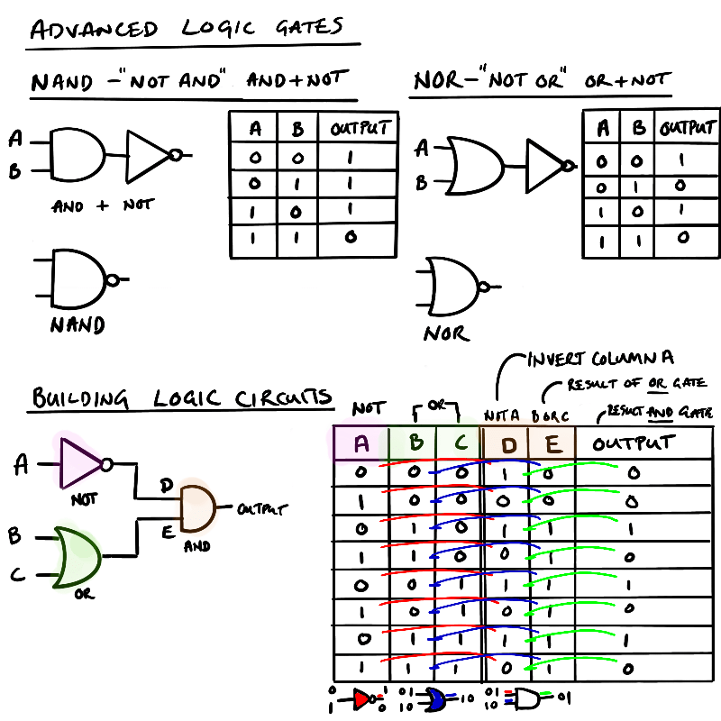
In electronics we use boolean logic and gates to build circuits. The AND, OR, and NOT gates are represented by symbols shown in the picture below and a Truth table that shows what the outputs would be based on the array of binary inputs.

You may be thinking that a NOT gate isn’t really a gate as it just flips the input coming in so there is no logical argument here unlike an AND or OR gate that does at least compare the state of two inputs and then produce something different. And you’d be right as the NOT gate is used to change or format a signal before and after AND and OR gates.
Adding the NOT gate after the AND or OR creates compound gates. These gates have an N added to the front to create NOT ADD – NAND, NOT OR – NOR. Whilst they are written in this order they are more accurately ADD + NOT, OR + NOT, as they NOT, or inversion happens after the signal of the first gate.
Logic Diagrams
The symbols for the NOT, AND, and OR gates allows for logical diagrams to be created to illustrate the logical flow of signals around a circuit. Starting with simple diagrams you can create a logical circuit which does something fun. Let’s play a game.
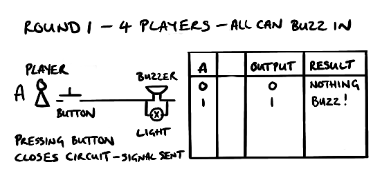
In this game there are four players and three round of questions where players have to buzz in where a light will also show.
Round 1 – all players have their own buzzer
Round 2 – players work in pairs where either player can buzz in and answer for the pair
Round 3 – still in pairs but both players have to buzz in to answer the question
The first round it’s simple – four independent circuits with a button, buzzer and light (nothing fancy where the first button press blocks the other circuits for now).
For the second round it gets a little more complicated as there are two buttons and a shared buzzer between two players so we need to add some logic to know the buzzer will go off if one of them presses their button.

We can do this using an OR gate. As you can see from the truth table above picture above when either player presses their button the buzz will sound and the light will light up.
Final round three it’s similar to the second round but both buttons have to be pressed for the buzzer to go off. In this case we two positive signals of the buzzer and light to go off.
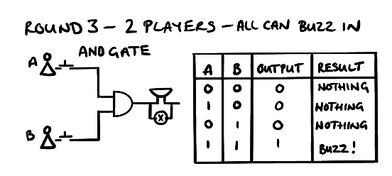
If we need two positive signals we need an AND gate as this checks for two signals before allowing a signal to progress.
One thing to stress when looking at logical gates in electronics is they are not what the actual circuit looks like. Logical gates are made up of transistors that we saw early where current can be switched into different tracks depending on how the program wants to run.
Truth Tables
One way to checking all the possible logic outcomes from a circuit is to write out all the possible scenarios that could happen and what the outputs would be. We do this using Truth Tables which are shown in the pictures above. Truth tables are simple to use when there is just one logic gate but become more complex more gates are added as there are more possible scenarios. But take your time and take each input and then work out what options there are after each step.
We saw in the picture on advanced logic gates how to work through a set of gates to show a truth table. In the example we have two gates to start: 1) NOT gate and 2) OR gate. The two outputs from these gates feed into an ADD gate. What are the possible outcomes from this logical diagram?
First draw out the gates so you can see the number of inputs and what the gate does. In this case a NOT gate with one input and an OR gate with two inputs. This gives three inputs – A, B, C. Each input has two options – 0 or 1 . This gives us 2 x 2 x 2 = 8 scenarios. This can also be written as 2^3 (binary options raised to the number of inputs). If you had 4 inputs then you would need 2^4 rows or 16.
Once you know the number of rows then you will need to fill in the rows for each combination. There are a couple of ways to do this. In the example below the NOT inputs (0,1) are run against the OR inputs (0,1:01).

The other way of doing this is to run through all the options to make sure you don’t miss one.
In the example above it would look like this where we count in binary from 0 to 7 starting at 000 (zero) to 111 (seven) which are our 8 rows. You can do it anyway you like to get to a full list of inputs. The inputs are colour-coded in the table below to help you follow how the process runs.
| Row No | Binary No | Input A | Input B | Input C | Input D (NOT A) | Input E (B OR C) | Output F D AND E |
|---|---|---|---|---|---|---|---|
| 1 | 0 | 0 | 0 | 0 | 0 > 1 | 0 OR 0 = 0 | 1 AND 0 = 0 |
| 2 | 1 | 0 | 0 | 1 | 0 > 1 | 0 OR 1 = 1 | 1 AND 1 = 1 |
| 3 | 2 | 0 | 1 | 0 | 0 > 1 | 1 OR 0 = 1 | 1 AND 1 = 1 |
| 4 | 3 | 0 | 1 | 1 | 0 > 1 | 1 OR 0 = 1 | 1 AND 1 = 1 |
| 5 | 4 | 1 | 0 | 0 | 1 > 0 | 0 OR 0 = 0 | 0 AND 0 = 0 |
| 6 | 5 | 1 | 0 | 1 | 1 > 0 | 0 OR 1 = 1 | 0 AND 1 = 0 |
| 7 | 6 | 1 | 1 | 0 | 1 > 0 | 1 OR 0 = 1 | 0 AND 1 = 0 |
| 8 | 7 | 1 | 1 | 1 | 1 > 0 | 1 OR 1 = 1 | 0 AND 1 = 0 |
Once the input fields for the gates are inputted then create two columns for the results coming out of the gate which will be the inputs going in the next gate. Here you do the same as the previous columns and work out the result when the inputs go through the gate to get to your final answer. The trick (and where the mistakes start) is getting the full set of inputs and getting the right rules for gate.
Logic and Programming
How is understanding logic gates helpful when trying to program a computer to do something? Understanding logic and logic gates is truly fundamental when designing, writing, and trying to fix computer programs that are not working the way you want them to as the data you are using will be sent through the program based on logical rules – boolean logic.
Boolean logic is so important to understand is that it’s the language the computer uses in its processing. You will know doubt have seen humanoid robots or androids from science fiction expressing a cold sentiment to a decision – “it is not logical”. The reason it has to be logical is back to those transistors we mentioned at the start – either the current flows, the circuit is on, or it doesn’t, it’s off. This idea of current flowing creates a binary, on/off, True/False situation. This is the basis of decision making in coding – is the thing true or false
Checking for Truth
A quick recap on the central processing unit (CPU). The CPU is made up of memory, program counter, accumulator and arithmetic and logic unit. The data and instructions and data are pulled through from memory to either the accumulator or the ALU. The ALU as the name suggest does arithmetic and logic operations.
There are three logic operations the CPU can do.
- Equal to (==)*
* = is use to assign something to a variable e.g. name = ‘Bob’ - Less than (<)
- More than (>)
For each of the above the result can generate a True or False. For example the following are true.
- Equal to (==)
a == a
5 == 5
apple == apple TRUE - Less than (<)
5 < 10
x < y (where x is a number) - More than (>)
10 > 5
x > y (where x is a number)
From a reading the above it all seems very obvious but it is worth taking a bit of time to think how it relates to the logic gates we saw earlier. How does a computer through transistors ‘know’ what is true or not true (false)?
For things that are equal it can check if the data is the same by comparing two sets of binary data 001100 = 001100 is a match therefore true. This can be used for any thing be that a number or a letters. But what about less than, or more than – how does that work? We, as humans we “know” there are three categories of numbers: negative, zero, positive. And from these numbers we “know” that 5 is bigger than 3 or 5million is bigger than 3million. But we know the order of these numbers so can we can work it out – you can ask a child a child what is bigger or smaller and they will know.
So how does a computer do this and how does this help understand how a computer works? By understanding how a computer gets to a binary result, true or false then it makes it easier to build programs. And there is an easy way to work it out – subtract one from the other.
Logic proven by subtraction
We can look at each of the logic decisions as results of subtraction.
For equals it’s straight forward if the result of the subtract is NOT positive or NOT negative then it’s equal. This would be if result from subtraction of two things is not positive AND is not negative then result is zero. Zero result is the same therefore True
- Equal to (==)
a – a = 0
5 – 5 = 0
apple – apple = 0
if result is 0 (not negative AND not positive) then result is the same and TRUE
For less than (<) the result is always a negative number (or NOT a positive number OR NOT zero (NOT negative OR positive).
- Less than (<)
5 – 10 = -5 (negative number)
x – y = -z (negative number)(where x is a number)
For more than (>) the result is always a positive number – the opposite of less than.
- More than (>)
10 – 5 = 5 (positive number)
x > y (where x is a number)
By knowing the computer really is doing simple maths to prove a truth to make a ‘decision’. Combining this knowledge with how a program flow in designed we covered in programming fundamentals with the three basic constructs used to control the flow of a program: 1) sequence, 2) selection, 3) iteration we really get to understand what’s happening.
Quick recap on program flow. A sequence is
Previous: Robust Programming < | Boolean Logic | > Next: Languages and Integrated Development Environment
